Helicopter Tail Rotors
Welcome once again my faithful students. Hope all has been severe clear and blue skies since last we met. Now, I must admit I was having one heck of a time coming up with a subject for today’s lesson, then into the room walked Roxy, my slightly overweight golden retriever. The only thing that dog loves more than sneaking a snack is to chase her tail. Not sure why, and perhaps I really don’t want to know. However, when I saw her going round and round I thought, Now that is what would happen to a helicopter if it didn’t have a tail rotor. Shazam. Thanks to Roxy, we now have something to talk about today. So, what keeps helicopters from chasing their tail during flight? Well, hang around and we’ll find out together. And thanks again, Roxy. Hmm, I wonder if mounting something on her tail would stop her from chasing it.
Helicopter tail rotors (or why the helicopter doesn’t chase its tail)
Torque
So, if we want to know how to keep the helicopter from chasing its tail we should discuss why on earth it would do so in the first place, right? The reason is torque, or as explained by our good friend Sir Isaac Newton “For every action there is an equal and opposite reaction.” One of the very first problems helicopter designers encountered when they tried to create a machine that could hover was the problem of torque reaction, and constantly getting dizzy proving Newton’s third law. As you know, a typical single main rotor helicopter has a rotor system mounted on a rotor mast. The helicopter engine supplies power so that the helicopter can turn the mast, and thus the rotor system connected to it. When the helicopter applies torque to the mast to spin it, there is an equal-and-opposite torque reaction which tries to turn the attached helicopter airframe (and the passengers inside) in the opposite direction.
Eliminating the Torque Reaction
Counter-rotating Rotors
One way to counteract the torque of a rotor turning clockwise is to have one mounted in the same plane spinning counter clockwise. This is what most of the early designers seemed to use as a way to cancel the torque. The advantage of these types of systems (co-axial, tandem, intermeshing) is that the torque is countered with no loss of power. When  50% of the torque is used to turn one rotor clockwise, and 50% of the torque is used to turn a second rotor counter-clockwise, the torque reactions balance out. 100% of the engine power goes into turning the lifting rotor systems. Sounds good so far, right? These systems, though, are very complex mechanically and require more maintenance man-hours. However, there are still several production helicopters that do use multiple counter-rotating rotors as a way to cancel out torque. Examples are (at right, viewing clockwise from top left photo) the Boeing-Vertol tandem rotor helicopters; Charles Kaman’s intermeshing rotor system; the Russian co-axial helicopter, the Hokum; and finally, we the V22 tilt-rotor, which uses counter-rotating prop-rotors in order to cancel out torque. The V22 system is similar to a tandem rotor system when in helicopter mode.
In my humble opinion, the tandem counter-rotating system is not as popular as the tail rotor because of the complicated mechanics involved as well as the expense in maintenance time and component cost. So thanks to Igor (when you are as old as I am you are allowed to call him by his first name) we have the ever-popular tail mounted, anti-torque stability systems, aka tail rotors.
Tail Rotors
I believe Igor was the first to settle on using a single rotor mounted at the rear of the helicopter as a way to counter the torque. And as I said earlier, this is the most popular arrangement in today’s helicopters. Sikorsky engineers actually experimented with many different configurations before selecting a single tail mounted rotor.
Now, even though the majority of helicopters produced use this method of counteracting torque, there are some problems with this method that counter-rotating rotor systems do not have. One major issue with tail rotors is that they rob an enormous amount of power. As a rule of thumb, tail rotors consume up to 30% of the engine power. Yeow! That is a bunch of power, isn’t it?
Next is that due to size, weight constraints and location, tail rotors are more susceptible to encounters with obstacles during maneuvers in close proximity to the ground. Because they are mounted at the rear of the helicopter out of the pilot’s sight, there is an increased possibility of helicopter accidents caused by the tail rotor smacking a rock, tree, fence (well you get the point) and losing all anti-torque capability. This of course will cause an immediate inadvertent interface with the ground due to the loss of horizontal and yaw stability.
Finally, tail rotors can be difficult to control accurately. Turbulence and crosswinds make it very challenging to hold a constant heading in a tail rotor-equipped helicopter. The workload is very high, and good results are difficult to achieve. Many larger helicopters end up being designed with a yaw stabilization system, which is essentially an autopilot for the tail rotor. Trust me, I know from personal experience that learning to hover is a very humbling experience. During my brief but exciting flight training, there was not a 100-yard spot large enough for me to hover within. The skill set required to fly a helicopter produced that infamous aphorism (a cool “cocktail knowledge” [CK] phrase) “Real pilots fly helicopters.”
Tail Rotor Aerodynamics
As you might expect, the tail rotor assembly shares many of the aerodynamic tendencies of the helicopter main rotor system. After all, the tail rotor is essentially identical to a main rotor only mounted sideways. The tail rotor is controllable in collective pitch, but is not capable of cyclic feathering, thus causing an issue of correcting for dissymmetry of lift. For a tail rotor system, cyclic feathering is attained through the “flapping” action of the tail rotor blades which counteract dissymmetry of lift.
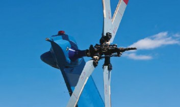
Tail Rotor Dissymmetry of Lift
Now you all remember the term “dissymmetry of lift” from our last session when we were going over helicopter terminology, right? When we discussed it, we concentrated on the main rotor system only. But it does make sense that tail rotors experience dissymmetry of lift just as a main rotor system does. (Tail rotor dissymmetry of lift will be discussed in greater detail during our next lesson.) For right now, suffice it to say that lift dissymmetry would cause a torque around the tail boom, which would tend to roll the fuselage in the same direction as main rotor lift dissymmetry. While cyclic pitch could be used to counter the rolling tendency, the tail rotor blades are typically allowed to flap, eliminating the lift dissymmetry. The photo at right shows a Bell 206 Jet Ranger tail rotor flapped to right and left extremes.
Tail Rotor Translational Lift
Just as a main rotor produces more lift when it moves into clean air, a tail rotor develops extra thrust when the helicopter moves it into clean air. Unfortunately, the pilot sees this as a change in anti-torque force, which results in an un-commanded yaw of the aircraft. The pilot is forced to make an adjustment to his anti-torque pedals as the tail rotor goes in and out of translational lift. There is no aerodynamic solution to this problem, and this is just one of the items that makes a tail rotor helicopter more difficult to fly. One solution that is sometimes used is a yaw-damper, essentially an autopilot that uses a gyroscope to detect un-commanded yaw, and then changes tail rotor pitch in order to prevent this exciting event.
Tail Rotor Settling with Power
Just as a main rotor can get into a ring vortex state by settling into its downwash, yawing the helicopter such that the tail rotor settles into its downwash (side-wash?) can and will induce the same ring vortex state. Indeed, a crosswind can induce the ring vortex state without any yaw being present. As I said, this is a somewhat rare occurrence, but it does happen and is just one more thing for the pilot to keep in mind.
The solution to this problem is similar to that for the main rotor: try to prevent it from happening, but if it does, either move the tail rotor into clean air (by moving the helicopter), autorotate (to eliminate the torque), or try to get out of the ring vortex state by a very rapid and large increase in thrust (but if the pedal is already at the stop, this probably isn’t possible). A hovering auto is probably the safest, most reliable way to get out of this situation, but as I am not a pilot, I will listen to any pilots who might have strolled into our class and will share some information. Any comments?
 Tail Rotor Coning
While some tail rotors may be designed to allow coning, all tail rotors that I am familiar with simply pre-cone the blades, and don’t worry about coning in the design. Helicopters with more than two blades (or more than two double stacked blades like the Hughes/MDHC-500) probably have a flapping hinge which acts as a coning hinge.
Changing the Pitch
In order to yaw the aircraft both right or left, the tail rotor blades need to be set to both negative and positive angles of attack, unlike main rotors which are normally only capable of positive angles of attack. The angle of attack of the tail rotor is controlled by the pilot’s anti-torque pedals; (don’t call them rudder pedals in a helicopter). The pedals are typically connected to the pitch change mechanism by either push-pull tubes or by cables. From the standpoint of controlling pitch, a tail rotor requires collective pitch control, but not cyclic feathering as has been stated earlier. This makes the pitch control mechanism of most tail rotors much simpler than that of the main rotor system.
And with that, I am going to release you for today, because I want you to remain curious and return again. During our next session we will discuss tail rotor dissymmetry of lift in detail, and then get into the details of pitch control mechanisms. In the following lesson, we will wrap up our sessions on tail rotors by talking about the Fenestron tail rotor system and finish that session with a quick review of the MD NOTAR system.
So there you have it. You still have enough time for an adult beverage, and you have information regarding the subjects for our next two lessons. See, I am always thinking of your health and welfare. With that, class is dismissed, and remember: even the best pilot can’t fly unless you say it is OK to fly
About The Author
Mike Broderick is V.P. of Business Development at Helicopter Engine Repair Overhaul Services (HEROS). Over the past 35 years, he has served as a shop technician, engine shop supervisor, Engine Program Director, Director of Maintenance, Director of Operations, and owner of a Rolls-Royce engine overhaul and MD Helicopter component overhaul shop. He is a certified A&P, and holds a Bachelor of Science degree in Aviation Administration. As well, Mike has been appointed as an FAA representative for the FAA Safety Team (FAAST) and is a member of the HAI Tech Committee. Mike is a regular contributor to Air Maintenance Update.
View all articles by Mike Broderick.