Helicopter tail rotors – III
Helicopter tail rotors …or why the helicopter doesn’t chase its tail – Part 3
Ready for the tail end of our discussion on helicopter Anti-Torque Systems (aka Tail Rotors)?…Hey, hey… no groaning there… OK, I know, 1,000 comedians out of work and I am still trying…but I couldn’t resist.
So anyway, I have checked my mail box and it appears you guys didn’t have any questions on what we have discussed to this point. Good, glad to see you all understand why helicopters need tail rotors and thus we can dispense with a review. So then whad’ya say we start examining the anti-torque solutions from our good friends at MD Helicopters and Eurocopter. The one from MD helicopters is called a NOTAR and the one from Eurocopter is called the Fenestron. Then, as promised, after we have gone through the workings of these two systems we will then wrap up with an explanation about that fun activity that all pilots love: Loss of Tail Rotor Effectiveness (LTE). And as always you can expect some neat Cocktail Knowledge (CK) along the way. Also, I should and will take the time now to thank all my friends at Bell Helicopter, MD Helicopters and American Eurocopter, as well as some very knowledgeable field technicians for their invaluable help on these sessions. So without further delay let’s get started.
NOTAR
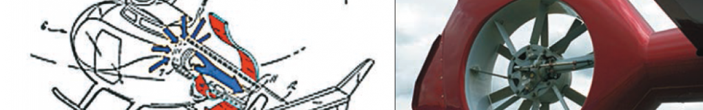
NOTAR is the name of a helicopter anti-torque system which replaces the use of a traditional bladed tail rotor like those we have been talking about in the last couple of class sessions. NOTAR was developed by McDonnell Douglas Helicopter Systems (through their acquisition of Hughes Helicopters). The name is an acronym developed from the phrase “no tail rotor”. The system uses a fan inside the tail boom to build a high volume of low-pressure air which exits through two slots and creates a boundary layer flow of air along the tail boom utilizing the Coanda effect. The boundary layer changes the direction of airflow around the tailboom, creating thrust opposite the motion imparted to the fuselage by the torque effect of the main rotor. Directional yaw control is gained through a vented, rotating drum at the end of the tailboom, called the direct jet thruster. Although the concept took over three years to refine, the NOTAR system is simple in theory and works to provide some directional control using the Coanda effect. A variable pitch fan is enclosed in the aft fuselage section immediately forward of the tail boom and driven by the main rotor transmission. This fan forces low pressure air through two slots on the right side of the tailboom, causing the downwash from the main rotor to hug the tail boom, producing lift, and thus a measure of directional control. This is augmented by a direct jet thruster and vertical stabilizers. Benefits of the NOTAR system include increased safety (the tail rotor being vulnerable), and greatly reduced external noise.
NOTAR-equipped helicopters are among the quietest certified helicopters. And the first question I see is: “Who or what is a Coanda?” Good question and sit tight because here you go. First the simple explanation and the first bit of CK: The Coanda effect is the tendency of a fluid jet to be attracted to a nearby surface. The principle was named after Romanian aerodynamics pioneer Henri Coanda, who was the first to recognize the practical application of the phenomenon in aircraft development. (See Figure 1) 
Notice the direction of item #6 the “Downwash”. The air wants to bend around the tail boom; what keeps it on track to “stick” around the underside is the air driven from the fan inside the boom and exiting from the slots on the tail boom. That is the simple explanation, but you want some first-hand proof which will amaze your friends and maybe even win you an adult beverage? Here is what you will need: a 12 to 14-ounce can; a candle which is shorter than the can; light the candle and put the can directly in front of the candle. Now blow on the can…the air will stick to the can and bend around it and put the candle flame out…Pretty cool, huh? Now that is some real usable cocktail knowledge.
History of NOTAR
Development of the NOTAR system began in 1975, when engineers at Hughes Helicopters began working with the concept development for an anti-torque system. In December 1981, Hughes flew an OH-6A fitted with NOTAR for the first time. The OH-6A helicopter (serial number 65-12917) was supplied by the U.S. Army for Hughes to develop the NOTAR technology and was the second OH-6 built by Hughes for the U.S. Army.
A more heavily modified version of the prototype demonstrator first flew in March 1986 (by which time McDonnell Douglas had acquired Hughes Helicopters). The original prototype last flew in June 1986 and is now at the U.S. Army Aviation Museum in Fort Rucker, Alabama. A production model NOTAR 520N (N520NT) was then produced and first flew on May 1, 1990. However on September 27, 1994 it was destroyed when it collided with an AH-64D while flying as a chase aircraft for the Apache. MD continues with its production of the NOTAR in both single engine MD 520N (Figure 2) and a twin engine version MD 902 (Figure 3). All right, now that I have warmed you up with info about NOTAR, how ‘bout we delve into what the French have brought to the table with their invention, the Fenestron.

Fenestron
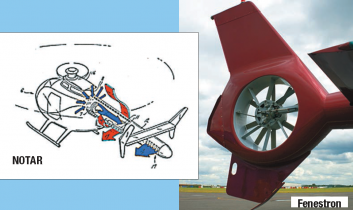
A Fenestron (or fantail, sometimes called “fan-in-fin”) is a shrouded tail rotor of a helicopter that is essentially a ducted fan. The housing is integral with the tail skin, and like the conventional tail rotor it replaces, it is intended to counteract the torque of the main rotor. It was originally conceived by Sud Aviation (now Eurocopter, soon to be Airbus Heliocpters, part of the European Aeronautic Defence and Space Company (EADS).
While conventional tail rotors typically have two or four blades, Fenestrons have between eight and 18 blades. These may have variable angular spacing so that the noise is distributed over different frequencies and thus sounds quieter. The housing allows a higher rotational speed than a conventional rotor, allowing it to have smaller blades. And you want some more CK? Here you go: the term Fenestron is a trademark of Eurocopter. It comes from the modern French for a small window, and is ultimately from the Latin fenestra (“window”).
 History of the Fenestron
In the 1960s, as helicopters were doing more specialized work in some very unconventional areas there was an increase of tail rotor strikes. It became obvious that the exposure to the working environment of the conventional tail rotor system was an issue requiring research into reducing sensitivity of the tail rotor to its environment. Paul Fabre, head of the Sud Aviation Aerodynamics department and specialist in seaplanes, under the supervision of head engineer René Mouille in the Design Office, designed a fan-in-fin shrouded rotor for the SA340. (See Figure 4).
The Fenestron (see inset) was born, though few grasped the significance of the innovation at the time. This first metal-bladed Fenestron had one curious feature: the blade on top was the advancing blade. Aware that this would have constituted an error on a conventional rotor, Fabre believed that on the Fenestron the effect of the main rotor downwash would be negligible. His judgment proved correct for the Gazelle because the Fenestron was always positioned two or three diameters from the ground, but when the problem appeared on the SA360 Dauphin, the direction of rotation of the Fenestron had to be reversed. (See Figure 5.)
The obvious superiority of the design prompted Sud Aviation to test the Fenestron on an SA330 Puma in 1975. But on a helicopter of such weight (seven metric tons), the tests proved disastrous. “This failure forced us to go back to the drawing board,” explains Bernard Certain. “We tried to improve on the design by constructing a prototype – the AS350 Z – which today has pride of place at the entrance to the Marignane site. The prototype enabled the Fenestron to become the reference design for a whole new generation of helicopters, the EC135, EC130, and EC155.” (See Figure 6 )


Nowadays all Fenestrons feature stators and “Chinese” (tuning) weights to reduce the power requirement and pitch control loads, with an even number of unevenly spaced blades designed to reduce noise levels.
As this picture denotes (Figure 7), this system is complicated but very effective. With this Fenestron design constantly evolving over the last 35 years, the Fenestron remains as important as ever. Indeed, with exciting challenges such as increased tonnages awaiting the Fenestron, we can expect to see more innovative evolutions. (See Figures 8, 9, 10 and 11.)
Advantages of the Fenestron:
• Increased safety for people on the ground, the enclosure provides peripheral protection
• Greatly reduced noise and vibration, due to the enclosure of the blade tips and the greater number of blades
• A lower susceptibility to foreign object damage, as the enclosure makes it less likely to suck in loose objects such as small rocks Enhanced anti-torque control efficiency:
A computational simulation has suggested that maximum achievable thrust is twice as high, and that at identical power, thrust was slightly greater, than for a conventional rotor.

 Disadvantages of the Fenestron:
The Fenestron’s disadvantages are those common to all ducted fans when compared to propellers.
• An increase in weight and air resistance brought by the enclosure
• Higher construction and purchasing cost
So there you have it: two different approaches to the counter acting main rotor torque from the US firm of MD the French firm of Eurocopter. Which one is better? Good question. Let me know what you think.
And before we leave this portion of the class today how ‘bout one more bit of CK. A little known fact about the origin of the Fenestron name. Paul Fabre, was born in Aix-en-Provence and very loyal to his roots. He chose the name “fenestrou”, which is a Provencal word meaning “small round window” as the name of his rotor invention. However, his boss, Francois Legrand, told him “no way”. Francois was not going to accept a colloquial deviation from the French langauge. Thus, Paul’s “Fenestrou” became the “Fenestron”.
OK now, as promised, here is our discussion on Loss of tail-rotor effectiveness (LTE): (LTE) occurs when the tail rotor of a helicopter is exposed to wind forces that prevent it from carrying out its function: that of cancelling the torque of the engine and transmission. Any low-airspeed high-power environment provides an opportunity for it to occur. And what causes LTE?
Environmental factors leading to LTE:
• Higher operating-density altitudes or temperatures, and high winds.
• A high gross weight will also instigate an LTE-conducive situation.
Causative wind-directions may include:
1. Main-rotor vortexes pushed into the tail rotor by wind. This can occur with wind coming from 10 o’clock on North American (counter-clockwise) rotors and from 2 o’clock on the main-rotor into the tail-rotor, preventing the tail rotor from having clean air to propel.
2. Wind from the tail (6 o’clock) can cause the helicopter to weathervane into the wind. The winds passing on both sides of the tail rotor make it teeter between being effective (providing thrust) and ineffective (not providing thrust). This creates a lot of pedal work for the pilot to eliminate unintended yaw.
3. Wind moving in the same direction as the tail rotor moves air. With pusher tail-rotors, that is wind from the opposite side of the tail-rotor. With puller tail-rotors, that is wind from the same side as the tail rotor. For main rotors with clockwise rotation (European), that is wind from 3 o’clock. For main rotors with counter-clockwise rotation, that is wind from 9 o’clock. The wind going through the tail rotor causes a stall condition as it decreases the effective airspeed of the air through the tail rotor. This condition will cause an unintended yaw that may develop into a spin. Recovery from this condition may be difficult if no airspeed is available, and will require entry into an autorotation (thus removing the torque of the engine and transmission).
And what clues tell the pilot that he is about to lose tail rotor effectiveness? How ‘bout an environment of low airspeed, and a demand for power, or better yet, an unintended yaw that may even be opposite to pedal input? As I said, although these might be subtle, and if it is at the end of the day and the pilot is tired, they just might not catch it until it is too late.
So can the pilot get out of an onset of LTE? Yes, recovery is initiated by increasing airspeed, using the vertical stabilizer to reduce yaw or, if uncorrectable by application of speed or tail-rotor thrust, entry into autorotation. Now, he doesn’t have to do a complete full Auto. Landing isn’t necessary; just the mere entry into autorotation will eliminate the torque, and then the spin or yaw will reduce through friction, particularly with the build-up of forward speed. At that point, power recovery (while maintaining airspeed) can be successfully accomplished. This maneuver requires skill as well as a quick reaction time. Kind of gives you a whole new perspective about helicopter drivers, huh? Next time you run into one at the local watering hole, buy them an adult beverage…they might have just successfully recovered from an LTE and would appreciate the drink.
So ends our Tail (sorry couldn’t resist again) on Anti-Torque systems. Once again, my thanks to my dog, Roxy, who gave me the inspiration, and all my tech-rep friends at Bell, MD and Eurocopter for their technical insight. With that, class is dismissed.
About The Author
Mike Broderick is V.P. of Business Development at Helicopter Engine Repair Overhaul Services (HEROS). Over the past 35 years, he has served as a shop technician, engine shop supervisor, Engine Program Director, Director of Maintenance, Director of Operations, and owner of a Rolls-Royce engine overhaul and MD Helicopter component overhaul shop. He is a certified A&P, and holds a Bachelor of Science degree in Aviation Administration. As well, Mike has been appointed as an FAA representative for the FAA Safety Team (FAAST) and is a member of the HAI Tech Committee. Mike is a regular contributor to Air Maintenance Update.
View all articles by Mike Broderick.