Helicopter Tail Rotors – Part 2
Well, I see you are here again for our continuing discussion on why helicopters, unlike my dog Roxy, don’t chase their tails. Welcome back, and thanks for coming. Let’s see: we finished up last time talking about how the tail rotor blades need to change pitch to control the yaw maneuver of the helicopter. Oh yeah, and I promised we would get into a more in-depth discussion about dissymmetry of lift. So whad’ya say we get started? But first, how ‘bout a review on changing pitch of the tail rotor.
Changing the Pitch
Now be patient; I know we spoke about this the last time, but it has been a while and a little review never hurts. We know that to yaw the aircraft either right or left, the tail rotor blades need the controllability to operate in both negative and positive angles of attack. And how is this different from the main rotor blades? Ah, see? A little review does help. Remember we discussed that the main rotors are normally only capable of positive angles of attack.
The changes to the tail rotor blade angle of attack is affected by the pilot’s anti-torque pedals, and please: all you fixed wing folks remember that these are not called rudder pedals in a helicopter. The pedals are connected to the pitch change mechanism by either push pull tubes or by cables. From the standpoint of controlling pitch, a tail rotor requires collective pitch control, but not cyclic feathering. Thus, the pitch control mechanism of most tail rotors is much simpler than that of the main rotor system. Now, here is a real statement of the obvious: The tail rotor blades must be mounted, and there must be a mechanism to change the pitch of the blades. Ya think? But this next statement may not be so obvious: Tail rotor blades also must be driven at an RPM ratio of about 3 times that of the main rotor.
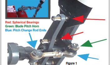
The tail rotor assembly pictured in Figure 1 is from a Robinson R22 tail rotor. You can clearly see how the blades are attached, and how the pitch change mechanism can pivot the blades. The red arrows point at the attachment points for the blade itself. These attachment points are bolts that go from one side of the yoke, through the blade, and into the other side of the yoke. The spherical bearing itself allows the blade complete freedom to rotate around the ball, to which the upper red arrow is pointing. Because there are two of these spherical bearings (you can see only the second one depicted by the red arrow) the blade is constrained to only move around an axis that is aligned between the two bearings. This allows the blade’s pitch (angle of attack) to be changed, but allows no other motion of the blade with respect to the yoke.
Notice that the bottom of the blade makes an “L” shape, with the green arrow pointing to the end of the “L” where a bolt goes through it. The “L” part of the blade, or pitch horn, gives leverage to change the pitch of the blade.
 The bolt that goes through the pitch horn also goes through a pitch change rod end (the right-hand blue arrow), which has one of those spherical bearings in it. This allows the rod end to push and pull on the pitch horn, thereby changing the pitch of the blade.
The other end of the rod end (the left-side blue arrow) is attached to the pitch change yoke.
The inset photo at the top left corner of Figure 1 shows another image of the same assembly from a very slightly different angle.
You can see the “L” shaped bottom of the blade better, and it’s a little more obvious how it attaches to the pitch change rod.
Figure 2 is the same assembly, except that now we are standing behind the helicopter looking directly forward at the tail rotor assembly.


 Figure 3: This picture shows how the pitch change mechanism moves the blades.
Figure 4: The red and green arrows show how the slider slides left and right on the shaft. The pitch change rods are connected to the slider, and so as the slider moves to the right, the pitch change rods move to the right, and take the blade pitch horn with them.
If you look carefully at the bottom orange arrows, you can see that the pitch change rod and the blade pitch horn have been moved to the right.
The upper orange arrow just points at the blade, which you can see is at a different pitch angle in the two pictures.
Figure 5: As you can imagine each manufacturer has its own idea as to how the tail rotor pitch change movement should be managed.In the next example, we will examine the Bell Helicopter design.
The two images in Figure 6 show components of a Bell 206 helicopter. Notice that the pitch change mechanism is quite different from the R22. The pitch change rod is actually a shaft which goes through the hollow shaft the tail rotor is mounted on. Note the tail rotor hub at two extreme pitch settings.
In the left hand picture, the red arrow shows that the inner shaft has been extended all the way to the right. The right-hand picture shows the same shaft has been retracted. As the inner shaft slides left and right, the pitch change rods are moved as well, and pull the blade pitch change horn along with the rod. The blue arrow points out how far the rod end has moved, taking the blade’s leading edge with it. Like the Robinson, the blade is mounted on two spherical bearings, which cause it to rotate only in the pitch axis.
Figure 7: This picture is from the Enstrom family of helicopters. The assembly pictured here is an F28A tail rotor. In the lower left corner of the picture, you can see the cable attaching to the pitch change mechanism. The Enstrom blades don’t attach with spherical bearings the way the Robinson and Bell do, they utilize a bearing pack to allow the blade to feather.
Figures 8 and 9: Next, let’s see how the French do it on their ubiquitous Eurocopter AS350 Series Helicopters. If you take a look at their idea, it is by far less complex than any of the previous systems we have discussed. Eurocopter have designed and incorporated two-blade, hingeless seesaw rotor with fiberglass roving spar. Pitch change is affected through spar twisting. The system is greaseless fail-safe design.
Dissymmetry of Lift
Now, as promised, let’s discuss dissymmetry of lift. The simple explanation is that this operational event during the rotation of both the main and tail rotor is the difference in lift that exists between the advancing half of the rotor disk and the retreating half. First, let’s review what happens to the main rotor. Please note that the assumption for this explanation is the rotor is turning counter-clockwise. So, dissymmetry of lift is caused by the fact that in directional flight, the aircraft relative wind is added to the rotational relative wind on the advancing blade, and subtracted from the rotational relative wind on the retreating blade. The blade passing the tail and advancing around the right side of the helicopter has an increasing airspeed, which reaches maximum at the three o’clock position. As the blade continues, the airspeed reduces to essentially rotational airspeed over the nose of the helicopter. Leaving the nose, the blade airspeed progressively decreases and reaches minimum airspeed at the 9 o’clock position. The blade airspeed then increases progressively and again reaches rotational airspeed as it passes over the tail.
Figure 10: Note the shaded circle in the picture labeled “REVERSE FLOW”. Blade airspeed at the outboard edge of the shaded circle is 0 knots. Within the reverse flow area, the air actually moves over the blade backwards from trailing edge to leading edge. From the reverse flow area out to the blade tip, the blade airspeed progressively increases up to 294 knots.
At an aircraft airspeed of 100 knots, a 200-knot blade airspeed differential exists between the advancing and retreating blades. Since lift increases as the square of the airspeed, a potential lift variation exists between the advancing and retreating sides of the rotor disk. This lift differential must be compensated for, or the helicopter would not be controllable. Two factors, rotor RPM and aircraft airspeed, control blade airspeed during flight. Both factors are variable to some degree, but must remain within certain operating limits. Angle of attack remains as the one variable that may be used by the pilot to compensate for dissymmetry of lift. The pitch angle of the rotor blades can be varied throughout their range, from flat pitch to the stalling pitch angle, to change angle of attack and to compensate for lift differential.
Figure 11 shows the relationship between blade pitch angle and blade airspeed during forward flight. Note that blade pitch angle is lower on the advancing side of the disk to compensate for increased blade airspeed on that side. Blade pitch angle is increased on the retreating blade side to compensate for decreased blade airspeed on that side. These changes in blade pitch are introduced either through the blade feathering mechanism or blade flapping. When made with the blade feathering mechanism, the changes are called cyclic feathering. Pitch changes are made to individual blades independent of the others in the system and are controlled by the pilot’s cyclic pitch control.
OK, did all that make sense? Hopefully it did. One thing’s for sure; there is at least a year’s worth (or more) of cocktail knowledge (CK) in that explanation. Use it and let me know what happens.
Tail Rotor Dissymmetry of Lift
Now that we understand how dissymmetry of lift affects the main rotor system, let’s move to the tail rotor. The tail rotor experiences dissymmetry of lift during forward flight because it also has advancing and retreating blades. Dissymmetry is corrected for by a flapping hinge action. Two basic types of flapping hinges – the delta and the offset hinge – are used on most contemporary helicopters.
Figure 12: The delta hinge is not oriented parallel to the blade chord. Figure 13: The hinge is designed so that flapping automatically introduces cyclic feathering, which corrects for dissymmetry of lift. The offset hinge is located outboard from the hub. To compare the lift of the advancing half of the disk area to the lift of the retreating half, the lift equation can be used. In forward flight, two factors in the lift formula – density ratio and blade area – are the same for both the advancing and retreating blades. The airfoil shape is fixed for a given blade. The only remaining variables are changes in blade angle of attack and blade airspeed. These two variables must compensate for each other during forward flight to overcome dissymmetry of lift.
So ends another session on one of the many the mysteries of helicopter flight. But don’t stray far, because next time we will finish our “tail” with an interesting discussion about two very inventive tail rotor systems. One from MD helicopters called a NOTAR, and one from our French friends at Eurocopter called the Fenestron. And then we will wrap up with an explanation about Loss of Tail Rotor Effectiveness (LTE). Now go forth my faithful students and remember: “A free ride and free food are two of the three things that no pilot ever turns down” … Dick Rutan.
About The Author
Mike Broderick is V.P. of Business Development at Helicopter Engine Repair Overhaul Services (HEROS). Over the past 35 years, he has served as a shop technician, engine shop supervisor, Engine Program Director, Director of Maintenance, Director of Operations, and owner of a Rolls-Royce engine overhaul and MD Helicopter component overhaul shop. He is a certified A&P, and holds a Bachelor of Science degree in Aviation Administration. As well, Mike has been appointed as an FAA representative for the FAA Safety Team (FAAST) and is a member of the HAI Tech Committee. Mike is a regular contributor to Air Maintenance Update.
View all articles by Mike Broderick.