
Today’s Composites

As the demand for lighter, stronger components grows, so does the importance of composite materials. But how is the structural integrity of a composite tested? Here’s a look at some of the basic methods.
Testing Composites
Composite materials are becoming more important in the construction of aerospace structures. Aircraft parts made from composite materials, such as fairings, spoilers, and flight controls, were developed during the 1960s for their weight savings over aluminum parts. New generation large aircraft are designed with all composite fuselage and wing structures, and the repair of these advanced composite materials requires an in-depth knowledge of composite structures, materials, and tooling. The primary advantages of composite materials are their high strength, relatively low weight, and corrosion resistance.
Composite materials consist of a combination of materials that are mixed together to achieve specific structural properties. The individual materials do not dissolve or merge completely, but they act together as one. Normally, the components can be identified as they interface with one another. The properties of the composite material are superior to the properties of the individual materials from which it is constructed. An advanced composite material is made of a fibrous material embedded in a resin matrix, generally laminated with fibers oriented in alternating directions to give the material strength and stiffness. Fibrous materials are not new; wood is the most common
fibrous structural material known to man.
Applications of composites on aircraft include:
• Fairings
• Flight control surfaces
• Landing gear doors
• Leading and trailing edge panels on the wing and stabilizer
• Interior components
• Floor beams and floorboards
• Vertical and horizontal stabilizer primary structure on large aircraft
• Primary wing and fuselage structure on new generation large aircraft
• Turbine engine fan blades
• Propellers
But with the growing importance of composite materials, the question begs itself: What are the procedures for Nondestructive Inspection (NDI) of Composites? These are a few.
Visual Inspection
A visual inspection is the primary method for in-service inspections. Most types of damage scorch, stain, dent, penetrate, abrade, or chip the composite surface, making the damage visible. Once damage is detected, the affected area needs to be inspected closer using flashlights, magnifying glasses, mirrors, and borescopes. These tools are used to magnify defects that otherwise might not be seen easily and to allow visual inspection of areas that are not readily accessible. Resin starvation, resin richness, wrinkles, ply bridging, discoloration (due to overheating, lightning strike, etc.), impact damage by any cause, foreign matter, blisters, and disbonding are some of the discrepancies that can be detected with a visual inspection. Visual inspection cannot find internal flaws in the composite, such as delaminations, disbonds, and matrix crazing. More sophisticated NDI techniques are needed to detect these types of defects.
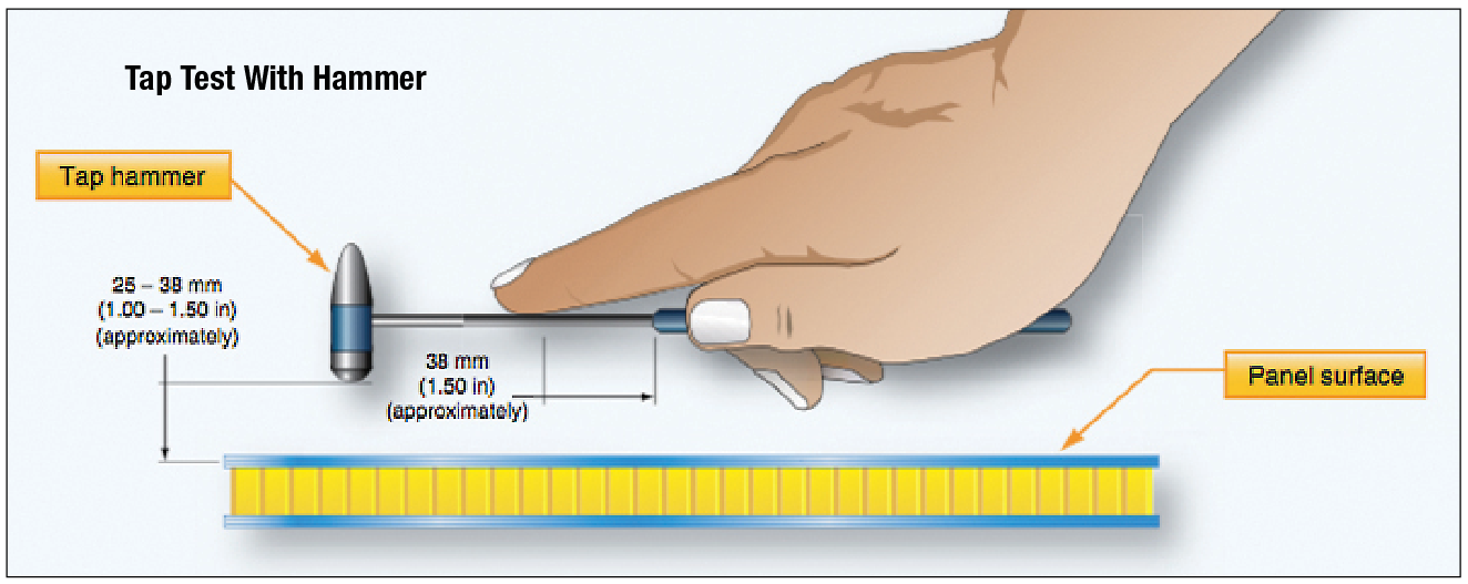 Audible Sonic Testing (Coin Tapping)
Sometimes referred to as audio, sonic, or coin tap, this technique makes use of frequencies in the audible range (10-20 Hz). A surprisingly accurate method in the hands of experienced personnel, tap testing is perhaps the most common technique used for the detection of delamination and/or disbond. The method is accomplished by tapping the inspection area with a solid round disk or lightweight hammer-like device and listening to the response of the structure to the hammer. A clear, sharp, ringing sound is indicative of a well-bonded solid structure, while a dull or thud-like sound indicates a discrepant area.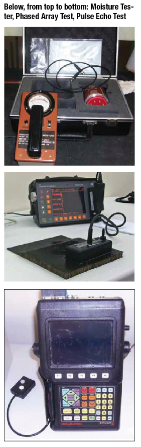
The tapping rate needs to be rapid enough to produce enough sound for any difference in sound tone to be discernable to the ear. Tap testing is effective on thin skin to stiffener bondlines, honeycomb sandwich with thin face sheets, or even near the surface of thick laminates, such as rotorcraft blade supports.
Again, inherent in the method is the possibility that changes within the internal elements of the structure might produce pitch changes that are interpreted as defects, when in fact they are present by design. Experienced personnel familiar with the part’s internal configuration should accomplish this inspection in as quiet an area as possible. This method is not reliable for structures with more than four plies. It is often used to map out the damage on thin honeycomb facesheets.
Automated Tap Test
This test is very similar to the manual tap test except that a solenoid is used instead of a hammer. The solenoid produces multiple impacts in a single area. The tip of the impactor has a transducer that records the force versus time signal of the impactor. The magnitude of the force depends on the impactor, the impact energy, and the mechanical properties of the structure. The impact duration (period) is not sensitive to the magnitude of the impact force; however, this duration changes as the stiffness of the structure is altered. Therefore, the
signal from an unflawed region is used for calibration, and any deviation from this unflawed signal indicates the existence of damage.
Ultrasonic Inspection
Ultrasonic inspection has proven to be a very useful tool for the detection of internal delaminations, voids, or in-
consistencies in composite components not otherwise discernable using visual or tap methodology. There are many ultrasonic techniques; however, each technique uses sound wave energy with a frequency above the audible range. A high-frequency (usually several MHz) sound wave is introduced into the part and may be directed to travel normal to the part surface, or along the surface of the part, or at some predefined angle to the part surface. You may need to try different directions to locate the flow. The introduced sound is then monitored as it travels its assigned route through the part for any significant change. Ultrasonic sound waves have properties similar to light waves. When an ultrasonic wave strikes an interrupting object, the wave or energy is either absorbed or reflected back to the surface. The disrupted or diminished sonic energy is then picked up by a receiving transducer and converted into a display on an oscilloscope or a chart recorder. The display allows the operator to evaluate the discrepant indications comparatively with those areas known to be good. To facilitate the comparison, reference standards are established and utilized to calibrate the ultrasonic equipment.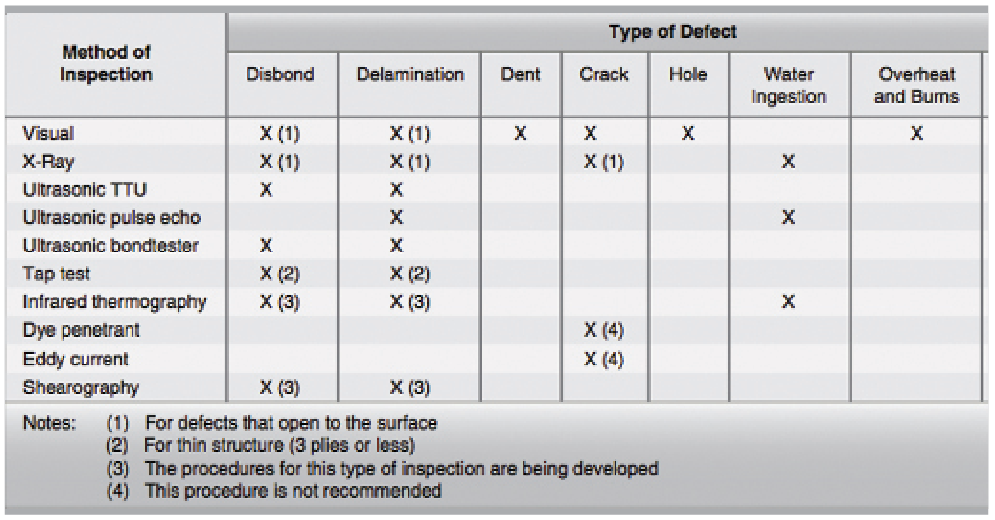
The repair technician must realize that the concepts outlined here work fine in the repetitious manufacturing environment, but are likely to be more difficult to implement in a repair environment given the vast number of different composite components installed on the aircraft and the relative complexity of their construction. The reference standards would also have to take into account the transmutations that take place when a composite component is exposed to an in-service environment over a prolonged period or has been the subject of repair activity or similar restorative action.
The four most common ultrasonic techniques are discussed next.
Through Transmission Ultrasonic Inspection
Through transmission ultrasonic inspection uses two transducers, one on each side of the area to be inspected. The ultrasonic signal is transmitted from one transducer to the other transducer. The instrument then measures the loss of signal strength. The instrument shows the loss as a percent of the original signal strength or the loss in decibels. The signal loss is compared to a reference standard. Areas with a greater loss than the reference standard indicate a defective area.
Pulse Echo Ultrasonic Inspection
Single-side ultrasonic inspection may be accomplished using pulse echo techniques. In this method, a single search unit is working as a transmitting and a receiving transducer that is excited by high voltage pulses. Each electrical pulse activates the transducer element. This element converts the electrical energy into mechanical energy in the form of an ultrasonic sound wave. The sonic energy travels through a Teflon or methacrylate contact tip into the test part. A waveform is generated in the test part and is picked up by the transducer element. Any change in amplitude of the received signal, or time required for the echo to return to the transducer, indicates the presence of a defect. Pulse echo inspections are used to find delaminations, cracks, porosity, water, and disbonds of bonded components. Pulse echo does not find disbonds or defects between laminated skins and honeycomb core.
Ultrasonic Bondtester Inspection
Low-frequency and high-frequency bondtesters are used for ultrasonic inspections of composite structures. These bondtesters use an inspection probe that has one or two transducers. The high-frequency bondtester is used to detect delaminations and voids. It cannot detect a skin-to- honeycomb core disbond or porosity. It can detect defects as small as 0.5-inch in diameter. The low-frequency bondtester uses two transducers and is used to detect delamination, voids, and skin to honeycomb core disbands. This inspection method does not detect which side of the part is damaged, and cannot detect defects smaller than 1.0-inch.
Phased Array Inspection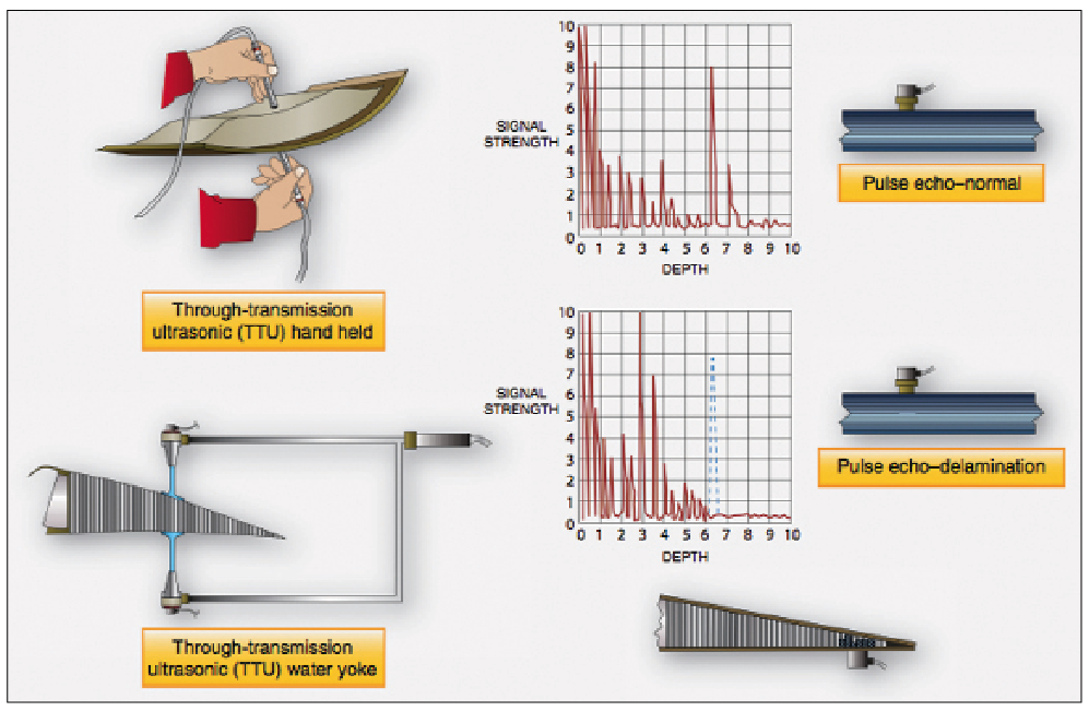
Phased array inspection is one of the latest ultrasonic instruments to detect flaws in composite structures. It operates under the same principle of operation as pulse echo, but it uses 64 sensors at the same time, which speeds up the process.
Radiography
Radiography, often referred to as X-ray, is a very useful NDI method because it essentially allows a view into the interior of the part. This inspection method is accomplished by passing X-rays through the part or assembly being tested while recording the absorption of the rays onto a film sensitive to X-rays. The exposed film, when developed, allows the inspector to analyze variations in the opacity of the exposure recorded onto the film, in effect creating a visualization of the relationship of the component’s internal details. Since the method records changes in total density through its thickness, it is not a preferred method for detecting defects such as delaminations that are in a plane that is normal to the ray direction. It is a most effective method, however, for detecting flaws parallel to the X-ray beam’s centerline. Internal anomalies, such as delaminations in the corners, crushed core, blown core, water in core cells, voids in foam adhesive joints, and relative position of internal details, can readily be seen via radiography. Most composites are nearly transparent to X-rays, so low energy rays must be used. Operators should always be protected by sufficient lead shields, as the possibility of exposure exists either from the X-ray tube or from scattered radiation. Maintaining a minimum safe distance from the X-ray source is always essential.
Thermography
Thermal inspection comprises all methods in which heat-sensing devices are used to measure temperature variations for parts under inspection. Thermal inspection consists of measuring or mapping of surface temperatures when heat flows from, to, or through a test object. All thermographic techniques rely on differentials in thermal conductivity between normal, defect free areas, and those having a defect. Normally, a heat source is used to elevate the temperature of the part being examined while observing the surface heating effects. Because defect-free areas conduct heat more efficiently than areas with defects, the amount of heat that is either absorbed or reflected indicates the quality of the bond. The type of defects that affect the thermal properties include debonds, cracks, impact damage, panel thinning, and water ingress into composite materials and honeycomb core. Thermal methods are most effective for thin laminates or for defects near the surface.
Neutron Radiography
Neutron radiography is a nondestructive imaging technique that is capable of visualizing the internal characteristics of a sample. The transmission of neutrons through a medium is dependent upon the neutron cross sections for the nuclei in the medium. Differential attenuation of neutrons through a medium may be measured, mapped, and then visualized. The resulting image may then be utilized to analyze the internal characteristics of the sample. Neutron radiography is a complementary technique to X-ray radiography. Both techniques visualize the attenuation through a medium. The major advantage of neutron radiography is its ability to reveal light elements such as hydrogen found in corrosion products and water.
Moisture Detector
A moisture meter can be used to detect water in sandwich honeycomb structures. A moisture meter measures the RF power loss caused by the presence of water. The moisture meter is often used to detect moisture in nose radomes.
(With FAA files)
About The Author
J. Campbell is an aviation enthusiast and advisor / writer / contributor to AMU Magazine for and about numerous topics in our maintenance industry. AMU Magazine would like to thank Mr. Campbell for his helpful assistance and expertise.
View all articles by J. Campbell.