
Engine Installation: Better Stick to the Plan
Previously, we looked at the standard protocols of piston engine removal. In theory, engine installation is simply the reverse procedure, right?
Last issue, we reviewed some of the considerations in preparing for the removal of a typical piston engine for repair or overhaul. (Read “Steps to consider when performing a piston engine removal” Dec/Jan. 2013-14.)
The installation of that same engine or an exchange engine after repair or overhaul is theoretically the removal steps in reverse, but with the right preparations to ensure that we have the necessary parts, tooling and equipment on hand. Planning ahead to ensure that all of the requisite resources are available will allow the installers to perform the job with minimal interruptions or delays.
The first step is to review the work order or task card to determine whether there are any other tasks to be done while the engine is out, and to become familiarized with the details for the install itself. For example, the engine may have been serviced with preserving oil, which would need to be drained before servicing with the recommended operating oil. It was suggested in the previous article that engine accessories should be cleaned, inspected and overhauled if necessary according to their instructions for continued airworthiness. Check that these items were already dealt with and are ready to be re-installed with the proper gaskets, mounting hardware, brackets, etc. Sometimes these components are re-installed as removed with no regard to checking the time in service or general condition of the component. All other engine related items such as the carburetor air box, breather tube and exhaust systems should be thoroughly cleaned, inspected for condition, and repaired as necessary before re-installation.
It is good practice to actually check the maintenance release details for the engine itself just to be sure that the specifics of the engine work were covered and all pertinent documents are available before proceeding. This serves as part of the overall quality control process covering all aspects of the job. Inspect the primary mounting hardware and replace if necessary. Also check on the status of any fluid-carrying hoses that may be due (or coming due) for replacement, SCAT hoses that are worn, torn or oil soaked. The rubber engine shock mounts are usually replaced at this time.
Inspect the engine controls carefully to verify that these items are still in serviceable condition and that they are not due for any special inspections or replacement according to the aircraft maintenance schedule. Don’t wait until any of these items are being re-installed to check them, as you want to ensure that they are ready and available as you progress through the installation process.
Once the engine has been lifted and set into place on its mount, be sure to follow any recommended procedures for securing the mounting bolts, mounts and spacers in a manner consistent with the best maintenance practices for that aircraft. Usually the initial placement and securing of the engine requires a few hands and a hoist operator ready at the controls. Some installations are rather straightforward and require minimal fuss while others require a more careful approach where retractable nose gear wells and fixed cowls become an additional challenge. Anybody who has done these before will undoubtedly have a tried-and-true procedure for coercing the engine into place with “a slight lift here and a gentle nudge there” until team success is realized. Good communication is necessary to maintain sufficient clearances as the whole process falls into place while ensuring that engine controls or wiring are not trapped out of position around the fixed engine mount.
Once the engine has been carefully mounted and secured into position, then the process of hooking up all of the necessary attachments can begin. In some cases, certain lines or hoses may be marked to help with orientation or for clarity of “which one goes where”. If pictures were taken of the previous installation, they should be referenced at this time to consider the best routing and positioning of engine controls, fluid lines or wiring. Use this installation process as an opportunity to make better choices regarding routing and orientation or to even correct previous methods that may be less than adequate.
Be especially vigilant when clamping or securing fluid- carrying hoses or wiring between the engine and the steel tubular mount. There must be enough slack in the routing of these items to allow for the natural vibration of the engine due to its positioning on the flexible rubber mounts.
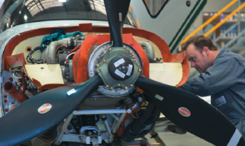
The propeller and associated spinner assembly must be installed in the proper orientation and torqued as per the manufacturer’s instructions. Be sure to track the propeller after torquing and safety lock the bolts as required. Engine and propeller combinations that have been previously dynamically balanced must be done again once the re-installation is complete. Checking engine and propeller combinations for dynamic balance is an excellent and often under-utilized tool to identify and correct vibrations inherent with the otherwise normal installation. It is also imperative that any installed modifications in the form of engine analyzers, heating elements or other approved installations are not altered in any way or conflict with the conditions of their installation and related instructions for continued airworthiness.
Completion of the engine installation should always be complemented with a good visual inspection from another person in order to identify any concerns resulting from a different set of eyes on the project. This is a highly recommended practice in other areas of aircraft inspection and is no less critical in this instance as well. Ensure that all clamps, gaskets, protective boots and hardware are accounted for by carefully reviewing your work area. Ensure that the top of the engine is looked over for any tools, shop rags or other foreign debris that may have been left behind. The top of the engine is often a convenient place to leave items that were in your hand one moment and gone the next!
All of the attached engine controls must be inspected by another person who has been trained in the performance of independent checks of control systems. This includes freedom and range of movement, binding, routing, attachment and safety locking. This is a critical inspection and must not be regarded as a quick formality performed in haste.
The theory of the independent (or dual) inspection is to ensure that we do not repeat the mistakes that have been previously documented in relevant human factors studies.
Some repair or overhaul shops may recommend a specific grade of mineral oil for engines that require cylinder break-in. Refer to the log book entry or warranty to verify any type of oil (or fuel) recommended for the break-in or warranty period. Ensure that the engine is serviced with the proper quantity of oil, and pre-oil the engine if required before start-up. The initial ground run procedure should be performed with the cowls off so that an observer can verify that there are no leaks once the engine is running.
The observer may also be responsible for the deployment of a portable fire extinguisher in the remote possibility that there is an engine fire. This person must be acutely aware of the propeller arc and not get too close to the front of the engine. I usually recommend standing away from the engine and within reach of the wing or wing-bracing strut for safety. If it is determined that there are no operating concerns or leaks from the engine, the cowls can be installed and a further run performed as needed. Proper engine cooling is dependent upon the positioning of the baffle seals. These may need to be checked once the cowls have been secured into place. A thorough checklist is a good tool that can be developed and utilized for the installation and ground run process.
The critical job of installing an engine usually requires a test flight to ensure that all engine systems are operating properly in the normal aircraft operating environment. In order to fly the aircraft after the groundwork is done, it is necessary for the AME to first complete a conditional maintenance release in the journey logbook. This includes the maintenance release for the work completed as well as the independent signatures and an attached requirement
for test flight.
Any information required for the final release of the aircraft must also be itemized by the AME and discussed with the pilot. The test flight after a conditional maintenance release must not be a normal revenue flight for commercial operators but should involve only essential crew to confirm the safety of the aircraft before it is returned to service. The pilot must enter a successful test flight as such into the logbook in order to finalize the release (that was only conditional upon a satisfactory test flight).
This overview should serve as a basis for considering the more foundational aspects of the engine installation process. Each engine installation job will require some very specific considerations, depending upon the type of aircraft and/or engine being maintained. Getting back to focusing on details should help address the complacent behaviours we tend to develop over time. Following detailed procedures and avoiding distractions remains instrumental throughout the performance of more involved tasks such as engine installation. More importantly, remember to follow the recommendations from the manufacturer as the basis for a well thought-out engine change process.
About The Author
Stuart McAulay resides near Cambridge, Ontario and enjoys the Brantford Flying Club.
View all articles by Stuart McAulay.