Helicopter Cocktail Knowledge
I know that you regular students are familiar with CK, but for you newbies, CK (or Cocktail Knowledge) is that useful bit of arcane information and/or minutia, which when shared in the right situation, will give you a perfect opening to begin a conversation or to interject comments into a conversation that has reached a point of stagnation.
Stick around, because today’s session is loaded with some really cool helicopter CK. Before we get started, though, you should know that the CK for today is provided by: my 40 years of hanging around helicopters and helicopter folks, some very good instructors at the OEM schools (like Bell Helicopters, Eurocopter, MD, Rolls Royce (formally Allison Engines), and Turbomeca, and finally that handy-dandy cornucopia of games and knowledge – the omniscient Internet.
So, please feel free to share this knowledge and impress your friends and family. And if you have some CK you want to share with me, you can find me at booth #N3615 during this year’s Heli-Expo convention or via email at mike@herosinc.com. I am always open to expand my CK.
OK, for our first bit of CK we will discuss the pilot in command (PIC) protocol for helicopters. How come the PIC in a helicopter sits in the right seat in most helicopters? Because helicopters are designed for right-handed people – really. Read on. The reason is mostly thanks to Mr. Sikorsky, though there can also be some operational justification.
Now, we all agree that helicopters are more inherently unstable than most airplanes, right? Basically, a fixed wing airplane wants to fly, while helicopters beat the air into submission. So with this law of physics in mind, a helicopter pilot rarely likes to let go of the cyclic stick (sit tight; we will talk about the cyclic in a bit) with his or her right hand, even with trim, and particularly in hover operations, where near-continuous control inputs are required.
In a normal flight profile, with the pilot sitting in the right seat, it stands to reason that the left hand which controls the collective, is also free to play with the radio buttons or mess with instrument knobs that are usually on a center console in a cabin with a side-by-side crew arrangement. Rotor brakes and clutches are also usually centrally located for the same reason.
OK? So how did Igor get involved? Well, when Igor Sikorsky built the world’s first mass-produced helicopter, the R-4, weight and engine power were big concerns. The R-4 was intended as a trainer, but was so underpowered that Sikorsky was looking for any potential weight savings. So, Igor and his engineers decided to let the instructor and student share a single collective. The only place to put it, then, was in the middle, between the two seats. Given the coordination and strength required to manipulate an R-4 cyclic for any length of time, the student (whom it was assumed would always be right handed) always flew from the right. Therefore, the first generation of U.S. Army Air Forces, Coast Guard, and Navy pilots – along with those from Britain and its Commonwealth, who learned on the R-4 and its follow-on, the R-6 (also with a single collective) – flew exclusively from the right.
However, leave it to the Yanks to buck tradition. In 1946, with the arrival of Bell’s Model 47 (the first civilian-certified helicopter), dual collectives were featured. From then on, dual collectives became standard for side-by-side seating, and a helicopter pilot could fly from either the left or right seat. See, I’ll bet you never thought about that, did you? You like that?
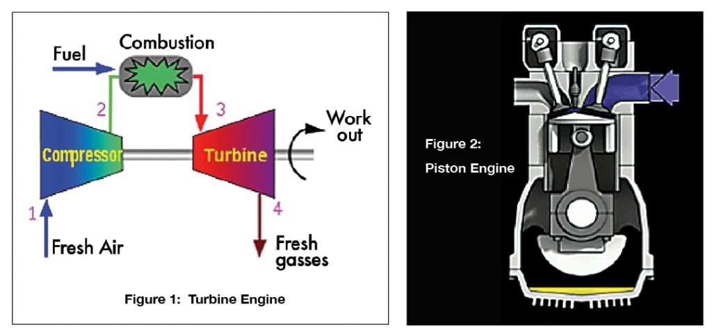
Good, sit tight, ‘cause here is CK #2. Did you know that the turbine engine is a 4-cycle engine like its cousin, the 4-cycle piston engine? Yup, it’s true. Look at these illustrations: (see Figures 1 and 2 above): intake (suck), compression (squeeze), combustion/power (bang), exhaust (blow). In the turbine engine, they call this process the Brayton or open cycle because each of these events takes place in a specifically designed section of the engine. And in the piston engine it is called the Otto or closed cycle because all of the action takes place in one spot, the cylinder affecting the movement of the piston.
OK, so you might have known this, but I’ll bet you didn’t know that George Brayton, an American engineer in 1872, is the guy responsible for identifying this activity in the turbine engine, and that Nickolaus Otto, a German traveling salesman in 1876 (go figure), is responsible for identifying this same action in the piston engine.
Now, interjecting that piece of interesting CK ought to spark enough energy into the even the most troublesome conversational doldrums. This next bit o’ CK is something you have thought about but couldn’t quite explain away. If you hover any distance above the Earth in a helicopter for a day or so, why aren’t you and the helicopter occupants on the other side of the world if the Earth is going through its normal rotation? Hmm. Good question, right? OK, well here is the answer: When you hover in a helicopter you are hovering in the air that is moving along with the Earth; thus the earth doesn’t move under you. In other words, the Earth and the air above it are moving around and around on the Earth’s axis together. I see some doubters out there, but it is true. Let’s think about this for a second. What would it be like if the air did not circle the Earth with us. Let’s consider what would happen if the air didn’t move with the Earth. Now, get ready for some math.
The Earth’s circumference is 24,901.55 miles (40,075.16 kilometers) at the Equator. The Earth travels this distance in one day, so that’s 40 million meters divided by 24 hours giving us about one and a half million meters per hour, or to you US students, about a thousand miles per hour. If the air in our atmosphere was not moving with the Earth, it would be blowing across the Earth’s surface at 1,000 miles per hour. Tough to stand upright, let alone hover a helicopter. Still not sure? Let’s say you are in a car, and your child is in the back seat, tossing a ball up and catching it. How come the ball doesn’t end up in the front seat with you? Because the air (aka atmosphere) in the car and the car are moving together.
OK, we are on a roll. What next? How ‘bout the term “dis-symmetry of lift”. This is a sure-fire conversation starter. Dis-symmetry of lift means the lift of the rotating blades is not symmetrical or equal. You see, when the rotor system is experiencing the airflow conditions all around the perimeter of the rotors’ arc, all things are equal, and the system is in balance. Once the system experiences a differential in wind speed from any angle, it becomes unbalanced, and begins to oscillate while in rotation. Take, for instance, forward flight. Imagine a two-bladed rotor system spinning at 100 mph (see Figure 3).
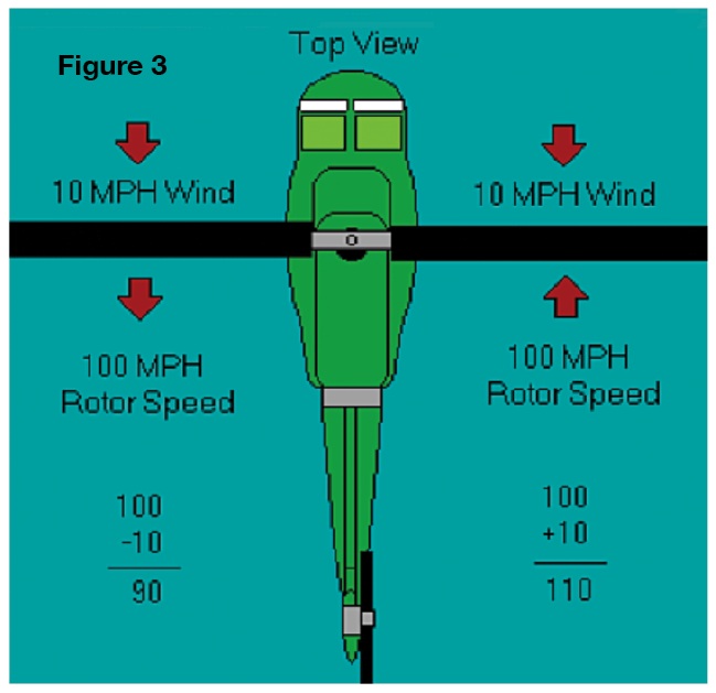
The blade moving toward the forward end of the aircraft is going 100 mph forward, and the blade moving toward the back of the aircraft is traveling at 100 mph in the other direction. This is just fine when the aircraft is not moving and there is in a no differential wind across the rotating disc. It is experiencing 100 mph of wind in all directions. The wind force across disc is in balance and the rotor is totally symmetrical in rotation. Once the aircraft moves forward though, it begins to change this balance. If we travel 10 mph forward, then the forward moving or advancing rotor blade is experiencing 110 mph of wind speed, and the rearward, or retreating blade, is experiencing only 90 mph of wind speed. When this happens, we get an unbalanced condition, with the advancing blade experiencing more lift wanting to climb while the retreating blade experiences less lift and wants to drop. This is where we get the term dis-symmetry of lift. The lift is not symmetrical around the entire rotor system.
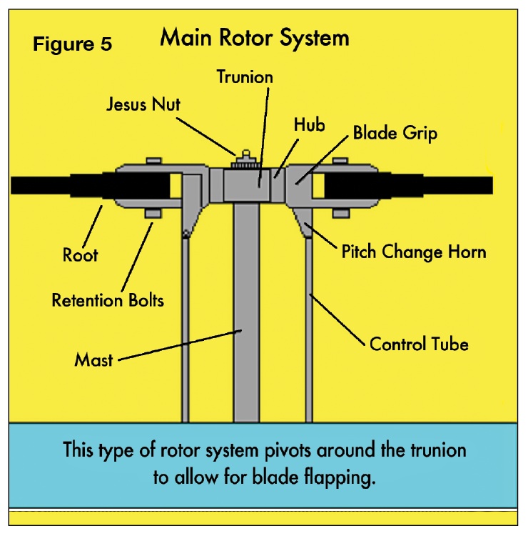
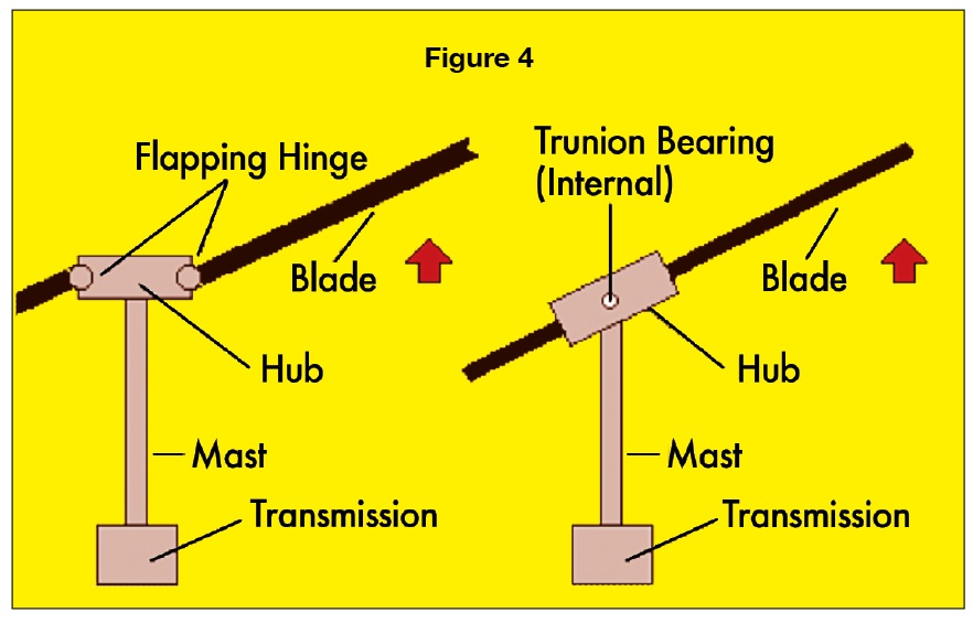 How do we counteract this situation? We compensate by allowing the rotor to flap. By allowing the advancing blade to flap upward and the retreating blade to flap downward, it changes the angle of incidence on both rotor blades, which balances out the entire rotor system. As you can see in Figure 4, there are a few ways to allow for blade flapping. One is to allow the blades to flap on hinges (articulated rotor system). Another way is to have the whole hub swing up and down around an internal bearing called a trunion (semi-rigid rotor system).
However, (you know there is always a however with helicopters), we cannot compensate completely for dis-symmetry of lift by using blade flapping. Once the aircraft gets to a certain airspeed, and the rotor has flapped as much as it is gonna flap, we now get to experience another cute trick exclusive to helicopters called retreating blade stall.
Retreating blade stall is when the retreating blade can no longer compensate for dis-symmetry of lift, which causes the outer portions of the blade to stall. This situation, if not immediately recognized, can cause a severe loss of aircraft controllability and thus could cause you to descend with the aerodynamics of a painted rock. Not a good thing for sure. The retreating blade stall phenomenon is a major airspeed limiting factor for helicopters. For many years, aeronautical engineers have tried to figure ways to eliminate this problem and increase the forward airspeed for single rotor helicopters.
Although ingenuity and technology have provided some cool advances in blade design, the manufacturers of single rotor helicopters have not been too eager to change the entire design on their products because of the extra costs involved for what has proven to be minimal airspeed for the investment. Most have resigned themselves to slower airspeeds for their aircraft, at a lower cost and less maintenance. Trust me, the operators like the idea of lower costs.
Well, I believe you have the beginnings of a great inventory of valuable CK for those awkward conversational moments. So whad’ya say: let’s finish our helicopter CK with a review of some helicopter terminology. And how ‘bout we start with the main rotor system.
Main Rotor System (Figure 5)
• Root: The inner end of the blade where the rotors connect to the blade grips.
• Blade Grips: Large attaching points where the rotor blade connects to the hub.
• Hub: Sits on top of the mast, and connects the rotor blades to the control tubes.
• Mast: Rotating shaft driven by the main rotor transmission. The mast connects the rotor blades to the helicopter.
• Control Tubes: Push/pull tubes that change the pitch of the rotor blades.
• Pitch Change Horn: The armature that converts control tube movement to blade pitch.
• Pitch: Increased or decreased angle of the rotor blades to raise, lower, or change the direction of the rotor’s thrust force.
• “Jesus” Nut (Main Rotor Retaining Nut): The singular nut that holds the hub onto the mast.
Why is it called the Jesus Nut? Because if it fails, the next person you see will be Jesus.
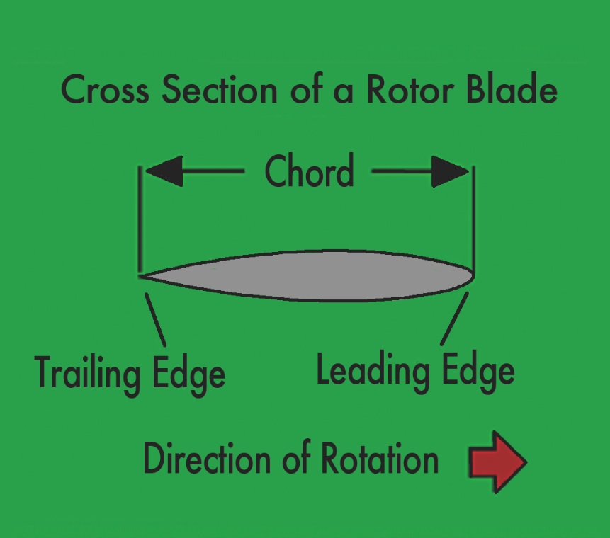
Main Rotor Blade (Figure 6)
• Leading Edge: The forward facing edge of the rotor blade.
• Trailing Edge: The back facing edge of the rotor blade.
• Chord: The distance from the leading edge to the trailing edge of the rotor blade.
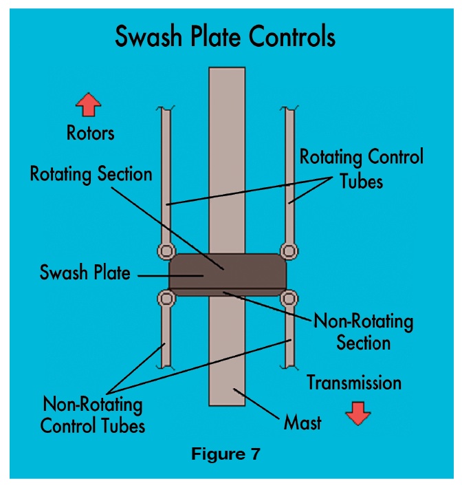
Controls (Figure 7)
• Swash Plate: Turns non-rotating control movements from the pilot into rotating control movements.
• Collective: The up and down control. It puts a collective control input into the rotor system, meaning that it puts either “all up”, or “all down” control inputs in at one time through the swash plate. It is operated by the stick on the left side of both the pilot’s and co-pilot’s seat.
• Cyclic: The left and right, forward and aft control. It puts in one control input into the rotor system at a time through the swash plate. And as we have already learned that the cyclic stick sits between the pilot’s legs, it is operated by the pilot’s right hand. (I know it’s a plot against us “lefties”).
• Pedals: On helicopters we don’t call them rudder pedals, although they are in the same place as rudder pedals on an airplane. A single rotor helicopter has no rudder. It has instead, an anti-torque rotor (also known as a tail rotor), which is responsible for counteracting the rotational forces of the main rotor. Pitch movement of the tail rotor blades is responsible for directional control at a hover and aircraft trim in forward flight. The pedals are operated by the pilots feet, just like airplane rudder pedals are. FYI: tandem rotor helicopters also have these pedals, but they operate both main rotor systems for directional control at a hover.
And with that, boys and girls, this class session on Helicopter Cocktail Knowledge is complete. Thanks for spending some time with me. Now your homework assignment is to go find someone to share all these now-known-to-you, arcane facts about the wonderful world of Helicopters.
About The Author
Mike Broderick is V.P. of Business Development at Helicopter Engine Repair Overhaul Services (HEROS). Over the past 35 years, he has served as a shop technician, engine shop supervisor, Engine Program Director, Director of Maintenance, Director of Operations, and owner of a Rolls-Royce engine overhaul and MD Helicopter component overhaul shop. He is a certified A&P, and holds a Bachelor of Science degree in Aviation Administration. As well, Mike has been appointed as an FAA representative for the FAA Safety Team (FAAST) and is a member of the HAI Tech Committee. Mike is a regular contributor to Air Maintenance Update.
View all articles by Mike Broderick.
